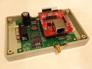
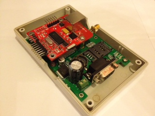
Here are some snapshots of the V1 in-car-module. Design is finalized, and in production now. Only change on production version (vs these) is some re-arrangement of the connector orientation and case holes.
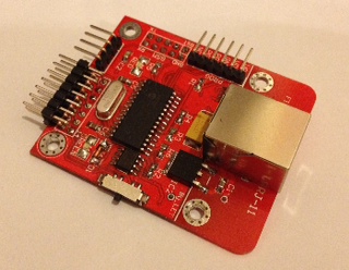
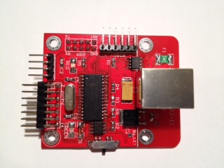
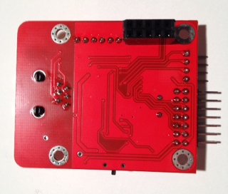
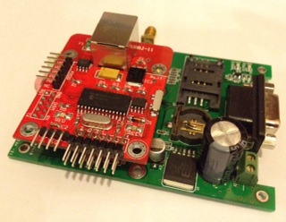
The CPU board. Based on a PIC microprocessor, the board includes CPU (ram+flash), power regulator, async line driver and CAN interface. We've spent some time working on the CAN interface design to isolate the can bus from the rest of the board as much as possible. You can see about 1/3rd of the board is completely bare with a white line that the can controller and power supply chips bridge. The blank side of the line is the CAN bus side and has as little as possible on it.


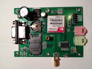
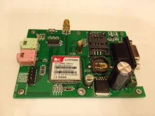
The MODEM board. Based on a SIMCOM SIM900 modem (with built-in IP stack). This is a very high quality GSM/GPRS modem. The design is based on an existing SIMCOM development board. Working with the factory, we've modified it to our needs, including arrangements for the CPU board to piggy-back on to it. We've left the debug ASYNC port and microphone/audio connectors in place, as those might be useful in future (or for other projects).

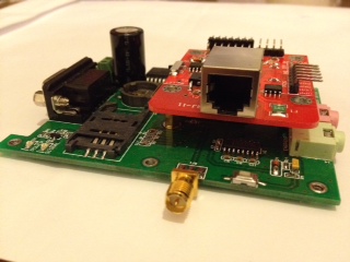
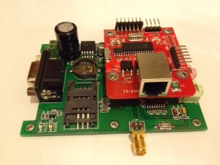
The two boards mated. As you can see, they mate together in a very sturdy piggy-back arrangement.


The box. The box is a pretty standard rectangular housing.
We've got lots of expansion here. We've brought out the unused pins from the CPU to allow extra modules to be connected in future. A microchip-standard 6pin connector is also there for in-circuit programming.